Arduino Inclinometer Improvements
After using the inclinometer for a while, it became apparent that the functionality was too basic. I extended it, so the unit tracks maximum pitch and roll values seen, displays the pitch and roll direction and can perform calibration on demand, so the unit does not have to acquire its orientation each time it is started up. I also built a better enclosure for it.
Source code
The source code for this project is available on GitHub, a previous blog post describes the parts list and hardware connections, the required Arduino libraries and how to build the software. It might be a good idea to at least briefly read the previous blog post, as this one does not go into the details explained there.
New enclosure
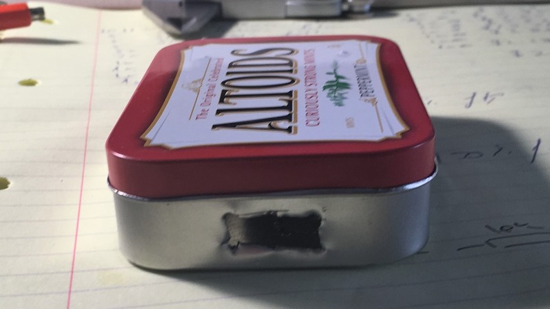
I was not happy with the original enclosure that I used for this project, as it was too big for the actual board. I also, unwisely, soldered the buzzer onto the PCB assembly and the buzzer was too tall, so I had to cut out a bit of the box to make room for the buzzer. The end result was not very nice, so I decided to look for another enclosure.
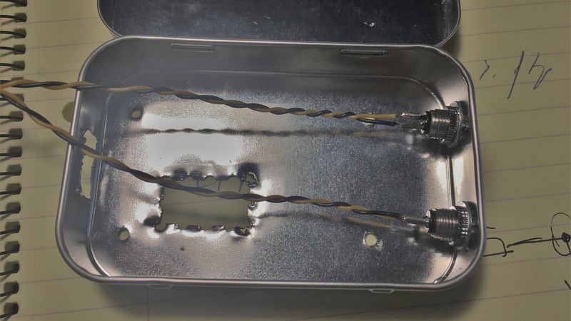
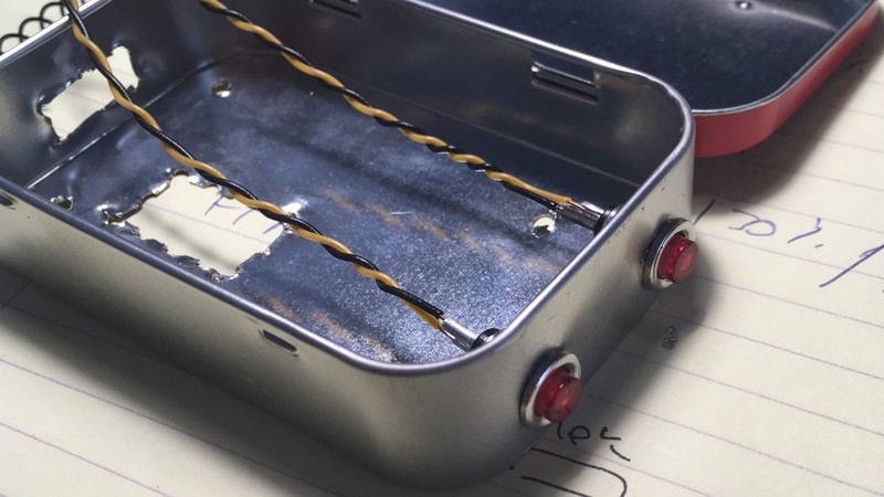
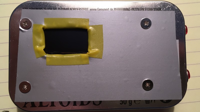
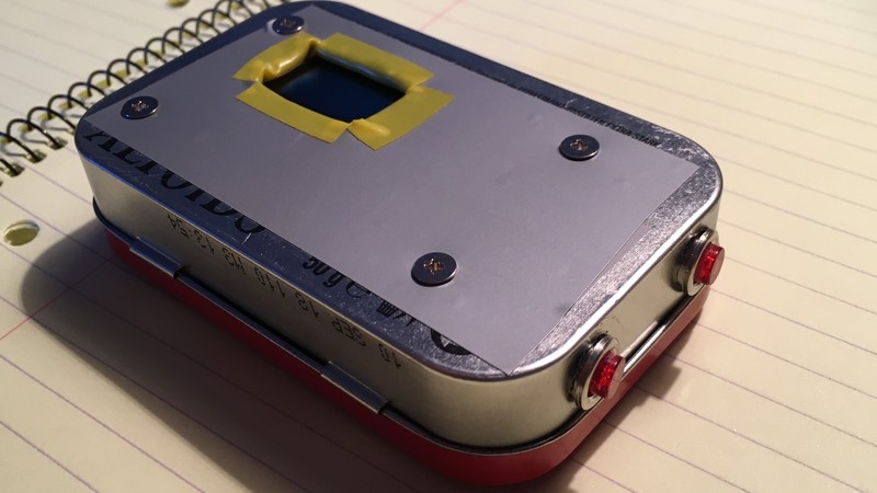
I spent a lot of time looking for plastic enclosures in electronics shops, but all the ones I found were either too big or too small. In the end, I found some mints in a tin box in a lolly shop, and the tin box was the exact size needed for my project. So the tin box only cost about $5.50 and I also got some mints.
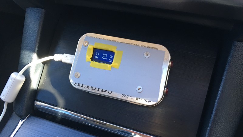
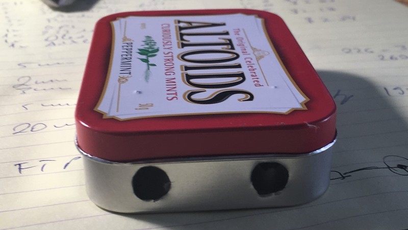
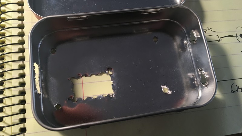
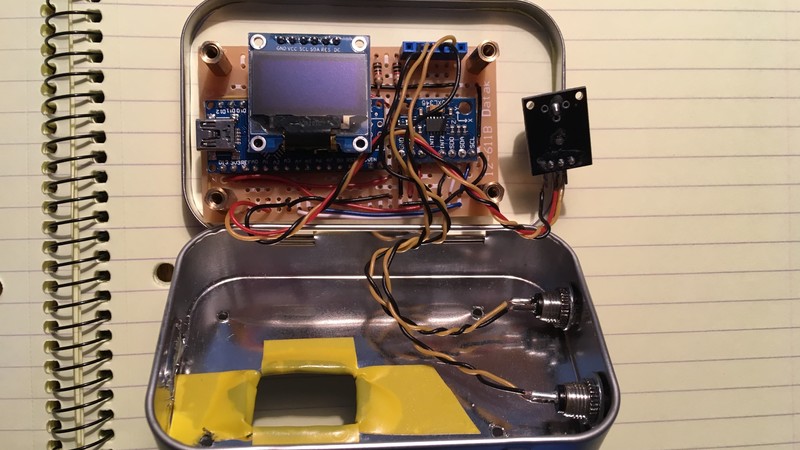
The new box fit perfectly the two new buttons (reset and calibrate) plus the PCB assembly and the buzzer, which I removed from the board and attached it to some wires, so the placement was more flexible.


Making room in the data memory
The first version of the program used most of the available data memory on the Arduino Nano board, with only 311 bytes remaining for function calls and local variables:
Sketch uses 19538 bytes (63%) of program storage space. Maximum is 30720 bytes.
Global variables use 1737 bytes (84%) of dynamic memory, leaving 311 bytes for local variables. Maximum is 2048 bytes.
Low memory available, stability problems may occur.
Before I could make any enhancements, which would use even more data memory, I had to free up some of this data memory. One thing I found out about the ATmega328P chip, which is what the Arduino Nano uses, is that string constants are stored in data space. For example, a simple Serial.println("Hello"), uses 6 bytes of data space (the string “Hello” and the terminating 0). Six bytes might not seem much on a normal computer, but the ATmega328P chip only has 2048 bytes of data memory.
The ATmega328P has a memory space to hold programs and a memory space to hold data. With my sketch, I had 11′182 bytes of program space left and I looked for a way for it to store some data. The program space cannot be changed at runtime, so it can only hold constant data, but the strings are constants, so they could be stored there.
The Arduino programing environment has the PROGMEM construct, which instructs the compiler to store the data in program memory. Unfortunately, this makes accessing the data more complicated, as the data stored in program memory cannot be accessed directly.
To put the constant strings into program memory, each string has to be declared using PROGMEM and all the strings have to be put in a separate table, string_table, which is also declared using PROGMEM. To print out a string, first it has to be copied back into a local buffer (which is in data memory), using strcpy_P, than it can be used. I wrote the oled_print_from_progmem function which wraps all this process and can be used to display constant strings, it uses an index instead of the string directly, but I also defined convenient constants for these strings.
1 2 3 4 5 6 7 8 9 10 11 12 13 14 15 16 17 18 19 |
const char string_0[] PROGMEM = "Roll"; const char string_1[] PROGMEM = "Pitch"; // ... other strings ommited const char* const string_table[] PROGMEM = { string_0, string_1, // ... other strings ommited }; // Name the string indices, for easy of use #define ROLL_STR 0 #define PITCH_STR 1 void oled_print_from_progmem(int text_size, int x, int y, int string_index) { char buffer[20]; oled.setTextSize(text_size); oled.setCursor(x, y); strcpy_P(buffer, (char*)pgm_read_word(&(string_table[string_index]))); oled.print(buffer); } |
The strings where using the most of the memory, however, I also put the CRC constant table in PROGMEM, this is used by the CRC function that validates the calibration stored in EEPROM (this is described below).
The end result is that, after adding functionality, and more data to the program, I still ended up 347 data memory available, compared with 311 bytes when I started:
Sketch uses 21474 bytes (69%) of program storage space. Maximum is 30720 bytes.
Global variables use 1701 bytes (83%) of dynamic memory, leaving 347 bytes for local variables. Maximum is 2048 bytes.
Low memory available, stability problems may occur.
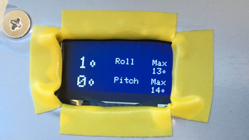
Updated display interface
The display of the unit was updated to show more information: the direction of the pitch and roll (up, down, left or right) is now displayed if the angle exceeds 1 degree, the maximum roll and pitch angles are also displayed. A “hold max” function will prevent the maximum angles to be updated, if that is the case, the max angles will blink.
Obtaining forward-backward and left-right information for pitch and roll angles
The previous code could calculate the roll and pitch angles, but it would not display the direction. That is, it might display a 2 degree roll but it would not show if it was left or right. For large angles, the direction is obvious for anyone who sits in the car, but for small angles, it is not. I extended the calculate_pitch function to return a negative angle if the vehicle is pitched up and a positive angle if it is pitched down. Similarly, the calculate_roll function was extended to return a negative angle for a left roll and a positive angle for a right roll. The display code was than updated to look at the sign of these angles and display the “up”, “down”, “left” and “right” strings, as appropriate.
When using the dot product to calculate angles, the angles always come out as positive, but we can look at the individual components of the acceleration vector to determine the orientation:
- the X axis is the forward-backward axis, so if the X component of the vector is positive, the “down” direction is pointing up, so the vehicle is pitched upwards
- the Y axis is the left-right axis, so if the Y component of the vector is positive, the “down” direction is pointing to the right, so the vehicle is rolling to the right.
The updated code is shown below, this section shows how the angles are actually calculated.
1 2 3 4 5 6 7 8 9 10 11 12 13 14 15 16 17 18 19 20 21 22 23 24 25 |
float calculate_pitch(float cal[3]) { float down[3] = {0, 0, 1}; float pitch_dir[3] = { cal[0], 0, cal[2] }; vnormalize(pitch_dir, pitch_dir); float pitch = vdot(down, pitch_dir); float angle = rad2deg(acos(pitch)); if (pitch_dir[0] > 0) return angle; // up else return -angle; // down } float calculate_roll(float cal[3]) { float down[3] = {0, 0, 1}; float roll_dir[3] = { 0, cal[1], cal[2] }; vnormalize(roll_dir, roll_dir); float roll = vdot(down, roll_dir); float angle = rad2deg(acos(roll)); if (roll_dir[1] > 0) return -angle; // right else return angle; // left } |
Keep track of the maximum pitch and roll angle
The unit will keep track of the maximum pitch and roll angles and will show these angles on the display. The angles can be in “hold mode” when they are not updated (in which case they will blink) and they can also be reset. Pressing the reset button for a short interval will toggle “hold mode” on and off. Pressing and holding the reset button for about a second will reset the max roll and pitch angles.
Updating the maximum angles is simple, they are stored in the max_pitch and max_roll global variables and are updated in the on_running function based on the current pitch and roll angle (they are only updated if the HOLD_MAX_FLAG is not set):
1 2 3 4 5 6 7 8 9 10 11 12 13 14 15 16 |
float max_roll = 0; float max_pitch = 0; void on_running(float cal[3]) { // ... other on_running() code ommited if (! IS_FLAG_SET(HOLD_MAX_FLAG)) { if (abs(pitch) > max_pitch) { max_pitch = abs(pitch); } if (abs(roll) > max_roll) { max_roll = abs(roll); } } } |
The more interesting part is dealing with the reset button. The reset button is wired to pin 11 on the Arduino, using a pull up resistor. As a side note, I only found out about the internal Arduino pull up resistors after I soldered my own external resistors to the board, if I knew about them earlier it would have saved me the trouble of soldering my own resistors. The reset button is active low, meaning that a digitalRead for the pin will read 0 if the button is pressed and 1 if the button is released.
Handling the reset button is done in the handle_reset_button function, which is called repeatedly as part of the loop function of the Arduino program.
To check if the button has been held down for about one second, the reset_hold_time global variable is incremented by delta_time each time the button is found to be pressed. Each time the button is released, reset_hold_time is set back to 0, so that the reset time is only counted for a single long press of the reset button. When reset_hold_time exceeds HOLD_INTERVAL, the maximum pitch and roll angles are set back to 0. delta_time represents the amount of time passed since the last loop invocation, it is set in the update_timer function.
When the button is released, that is, digitalRead reads a 1, the HOLD_MAX_FLAG is toggled, to enable or disable the update of the maximum roll and pitch angles. Before the flag is toggled, the code checks to see if the button was held down for a short period, by checking the value in reset_hold_time, this prevents accidental presses and helps with debouncing the signal from the button.
1 2 3 4 5 6 7 8 9 10 11 12 13 14 15 16 17 18 19 20 |
#define HOLD_INTERVAL (1000000) // microseconds #define RESET_PIN 11 int32_t reset_hold_time = 0; void handle_reset_button() { if (digitalRead(RESET_PIN) == 1) { if (reset_hold_time > (HOLD_INTERVAL / 10) && reset_hold_time < HOLD_INTERVAL) { TOGGLE_FLAG(HOLD_MAX_FLAG); } reset_hold_time = 0; } else { reset_hold_time += delta_time; } if (reset_hold_time > HOLD_INTERVAL) { max_pitch = max_roll = 0; CLR_FLAG(HOLD_MAX_FLAG); } } |
On demand calibration
The inclinometer unit can be installed in any position inside a vehicle and can determine its own orientation. This simplifies the installation process, as the alternative would have been to install the accelerometer unit aligned with the forward direction of the car. In the first version of the software, the unit would determine its own orientation every time it is powered up, however this requires the vehicle to be on flat ground when the unit is powered up and this is not always possible.
To avoid this situation, the new software will save the orientation matrix to EEPROM and restore it at power up. The unit will only enter calibration when the calibrate button is held down. The calibrate button is wired to pin 12 on the Arduino Nano board with a pull up resistor, just like the reset button. A similar technique is used to make sure the button is held down for one second before the unit enters calibration mode. The handle_calibrate_button works like the handle_reset_button function, but, since the calibrate button has no function when it is held down briefly, the resulting code is simpler.
To enter calibration mode, the function will set the state of the program to STATE_ACQUIRE_DOWN_DIRECTION, which is the first calibration step, and will also reset the internal state of the program.
1 2 3 4 5 6 7 8 9 10 11 12 13 14 15 16 17 18 19 20 21 22 |
#define HOLD_INTERVAL (1000000) // microseconds #define CALIBRATE_PIN 12 int32_t calibrate_hold_time = 0; void handle_calibrate_button() { if (digitalRead(CALIBRATE_PIN) == 1) { calibrate_hold_time = 0; } else { calibrate_hold_time += delta_time; } if (calibrate_hold_time > HOLD_INTERVAL) { SET_STATE(STATE_ACQUIRE_DOWN_DIRECTION); // reset the Z-Axis so it is acquired again vzero(orientation.zaxis); // Clear all state flags CLR_FLAG(HOLD_MAX_FLAG); CLR_FLAG(PITCH_WARN_FLAG); CLR_FLAG(ROLL_WARN_FLAG); } } |
The calibration data are the xaxis, yaxis and zaxis vectors determined from the calibration. These are saved to EEPROM at the end of calibration and restored when the unit is powered up. To prevent against data corruption, for example, when the unit looses power while writing new calibration data to EEPROM, the data is protected by a 16bit CRC checksum, and will only be used if it is valid.
1 2 3 4 5 6 7 8 9 10 11 12 13 14 15 16 17 18 19 20 21 22 23 24 25 26 27 28 29 |
#define EEPROM_CALIBRATION_ADDRESS (0) struct orientation_t { float xaxis[3]; float yaxis[3]; float zaxis[3]; } orientation; void save_calibration_to_eeprom() { uint16_t crc = calculate_crc((uint8_t*)(&orientation), sizeof(orientation)); EEPROM.put(EEPROM_CALIBRATION_ADDRESS, orientation); EEPROM.put(EEPROM_CALIBRATION_ADDRESS + sizeof(orientation), crc); } void restore_calibration_from_eeprom() { uint16_t stored_crc; EEPROM.get(EEPROM_CALIBRATION_ADDRESS, orientation); EEPROM.get(EEPROM_CALIBRATION_ADDRESS + sizeof(orientation), stored_crc); uint16_t crc = calculate_crc((uint8_t*)(&orientation), sizeof(orientation)); if (crc == stored_crc) { SET_STATE(STATE_RUNNING); } else { vzero(orientation.zaxis); // reset the Z-Axis so it is acquired again SET_STATE(STATE_ACQUIRE_DOWN_DIRECTION); } } |
Conclusions

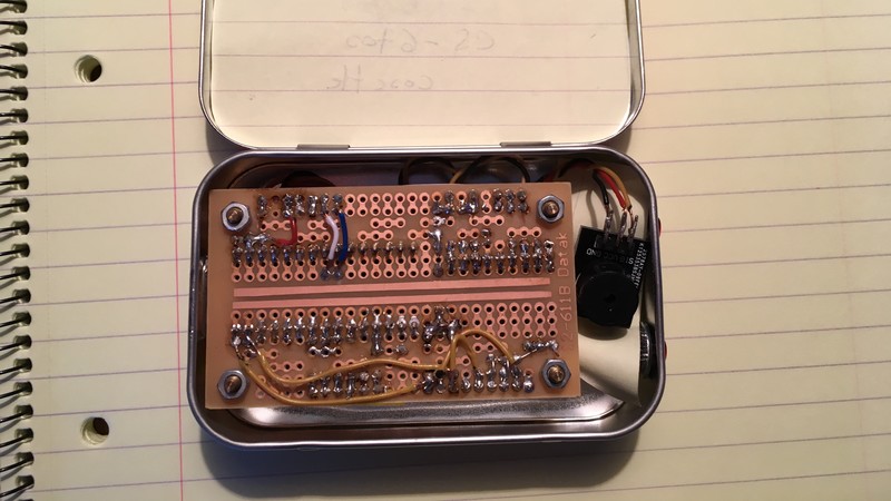
This has been an interesting project for me. As an experienced software engineer, the software itself was not a big challenge, but soldering everything together and preparing the enclosure was something that I did for the first time. You can see that from the quality of my soldering and the enclosure cutouts, but I did gain some experience from doing it. On the software side, I was pleasantly surprised by the amount and complexity of the code that the Arduino environment can handle. When I first contemplated the project I thought, I would have to leave out the nice Arduino libraries and program everything as low level AVR code to access the hardware registers and use fixed point math for the vector and matrix calculations. However, this was not the case: the entire program is written using high level libraries and functions, which is very nice.
The source code for this project is available on GitHub, a previous blog post describes the parts list and hardware connections, the required Arduino libraries and how to build the software.