Arduino Inclinometer
My brother-in-law got himself a 4WD and wanted an inclinometer module to display the roll and pitch of the vehicle while going on his adventures. I build one using an Arduino Nano and an accelerometer module.
Update 10 Mar 2018 There is an updated blog post with some improvements I made to the unit. If you liked this blog post, you might want to have a look at that one as well.
I found another Arduino based inclinometer project here, but, while I liked the design and component list, the actual Arduino sketch (program) was written in such a way that it required the actual accelerometer unit to be installed flat inside the vehicle and with the X axis of the unit facing forward. The accuracy of the roll and pitch readings depended on how precisely the unit is mounted inside the vehicle.
The model that I built uses the same parts list, but the Arduino Sketch can determine the orientation of the unit, so the unit can be installed in any position inside the vehicle: mine was attached with a piece of Velcro tape to the dash board.
Since the unit can be mounted in any position, the “down” direction read from the accelerometer will not be a reading of 1 for the Z axis, instead it will be an arbitrary reading of the X, Y, and Z axis values. When the unit is powered up, it will determine its “down” direction — this requires the vehicle to be on a flat surface. Once it knows the down direction it can determine the forward direction when the vehicle moves forward, as some acceleration applied to the unit. The forward direction can also be acquired by starting to move the vehicle and than immediately braking hard. With the “down” and “forward” directions acquired the unit can now interpret any accelerometer reading relative to these directions so it is being able to correctly determine the pitch and roll and display it.
Source Code
The source code for the project is available on GitHub. The working of the program is explained in the “The Arduino Sketch Explained” section below.
To successfully compile the sketches in this project, the following libraries need to be installed in the Adruino IDE. I used version 1.8.5 of the IDE, but any later version should work. To install a library, go to the Library Manager use the “Sketch/Include Library/Manage Libraries…” menu.
- Adafruit Unified Sensor — this is the sensor library requied by the ADXL345 library
- Adafruit ADXL345 — this library communicates with the accelerometer module.
- Adafruit GFX Library — this library is the base graphics library for drawing on the OLED display
- Adafruit SSD1306 — the display driver for the specific OLED display used in this project.
In addition to this, the Adafruit_SSD1306.h header file needs to be updated to enable theSSD1306_128_64 define, since this project uses an 128 x 64 pixel OLED display. This file can be found in the library folder. On Windows, libraries are installed in the “Documents/Arduino/libraries” folder.
Parts List
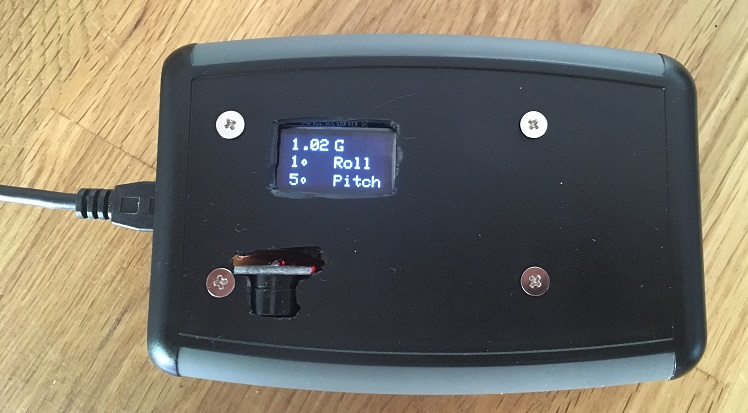
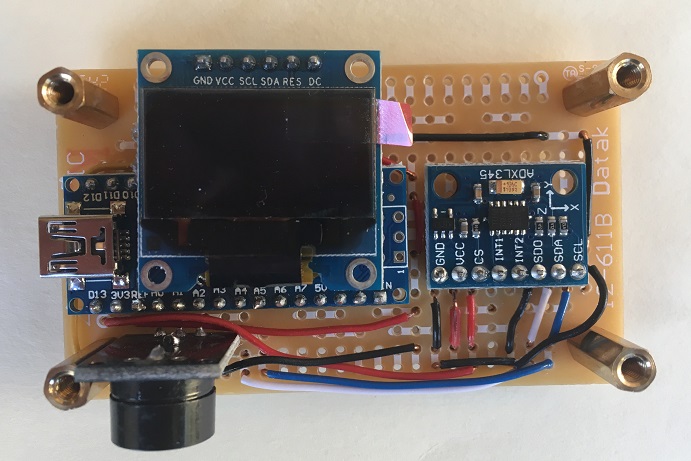
This is how the final unit looks. I bought a plastic enclosure to hold the PCB and modules and had to make cutouts for the screen and the buzzer module which would not fit inside the enclosure I got. The following parts are used by this project:
- Arduino Nano or compatible (ATmega328P microcontroller)
- OLED–12864 — 0.96 Inch White SPI OLED Display Module, based on the SSD1306 chip
- GY–291 — ADXL345 Digital Triple Axis Accelerometer Module — this module determines the orientation of the unit and is used to determine the roll and pitch angles.
- 3.5–5.5V Passive Buzzer Module For Arduino — this is used to sound an alarm when the roll or pitch angles exceed certain values
Connecting things together
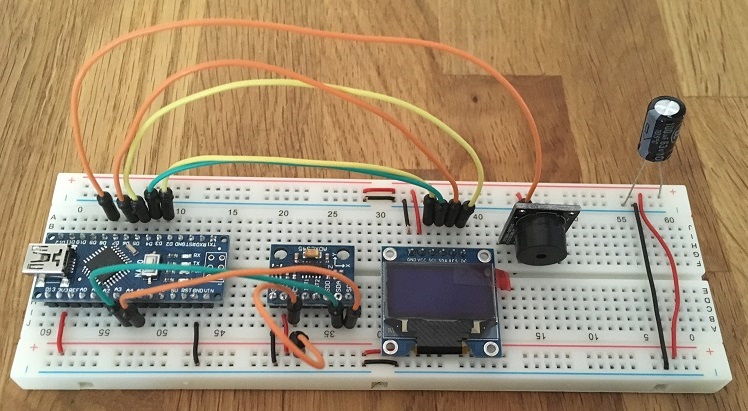
Before soldering things together, it is a good idea to first connect all components on a bread board and made sure everything was working properly. The actual connections between all the components are listed below.
Arduino Nano Connections
A4connected to ADXL345SDApinA5connected to ADXL345SCLpinD3connected to OLEDDCpinD4connected to OLEDRESpinD5connected to OLEDSDApinD6connected to OLEDSCLpinD8connected to the BUZZERSIGpin
ADXL345 Accelerometer Connections
GNDconnected to groundVCCconnected to the 3.3 Volt pin on the Arduino NanoCSconnected to 3.3 Volt pin on the Arduino Nano, so the chip is put in I2C mode.INT1not connectedINT2not connectedSDOconnected to ground (to select I2C address 0x53)SDAconnected to theA4pin on the Arduino NanoSCLconnected to theA5pin on the Arduino Nano
OLED Display Connections
GNDconnected to groundVCCconnected to 3.3 Volt pin on the Arduino NanoSCLconnected to theD6pin on the Arduino NanoSDAconnected to theD5pin on the Arduino NanoRESconnected to theD4pin on the Arduino NanoDCconnected to theD3pin on the Arduino Nano
Buzzer Module Connections
SIGpin connected to theD8pin on the Arduino NanoVCCpin connected to the 3.3 Volt pin on the Arduino NanoGNDpin connected to ground
Calibration
To increase the accuracy of the accelerometer, a static calibration needs to be done. Here is why: for each axis, the accelerometer can read a value between –1024 and +1024. The maximum acceleration range can be specified at initialization time, and for this application is set to 4 G. This means that, when 4 G of acceleration is applied to one of the X, Y or Z axes, the accelerometer should read 1024 (if 4 G is applied in the opposite direction, it should read –1024). If 1G is applied to the same axis, the accelerometer should read 1024/4 = 256.
The 1 G case is easy to test, since this is the Earths gravity. If you place the accelerometer flat on the table, 1 G of acceleration is applied to the Z axis, and zero acceleration on the X (forward) and Y (left) axis. If I do this experiment with my unit I get the following readings: “X = 5; Y = –27; Z = 226”. In fact, no matter how much I adjust the position of the accelerometer, I was never able to obtain the expected “X = 0; Y = 0; Z = 256” reading.
The calibration process obtains two adjustment values for each axis, a slope and an intercept. These values are used to adjust the value read from the accelerometer so that it will read –256 if –1 G is applied to an axis and +256 if +1 G is applied to that axis.
The calibration process described here is somewhat simplistic, but it works in this case because it is used to determine roll and pitch when there is little or no acceleration applied above the Earths gravity. The advantage of this process is that it is simple enough to perform and requires no extra tools or calibration rig. If the accelerometer is used to actually measure larger accelerations, a different process will need to be used — you will need to search the net for a better process.
How to perform the calibration and determine the slope and intercept
NOTE: calibration should be performed after the unit has been assembled and soldered on the final PCB, as soldering will change the calibration values.
The calibration sketch can help with the calibration process. This sketch prints out the raw accelerometer readings for the X, Y and Z axis. To view the values, open the serial monitor window on the Arduino IDE and make sure the serial speed is set to 38400 baud.
With this sketch running, six readings must be obtained from the accelerometer, two for each axis. The accelerometer module has the X and Y axes printed on the PCB, it may help to locate them now. Here are the six readings, when the accelerometer is placed:
- flat on the table (Z axis pointing up), adjust it until you obtain the maximum reading for the Z axis and make a note of it.
- upside down on the table (Z axis pointing down), adjust it until you obtain the minimum reading for the Z axis and make a note of it.
- standing on the table (X axis pointing up), read the maximum value for the X axis
- standing upside-down on the table (X axis pointing down), read the minimum value for the X axis
- sideways on the table (Y axis pointing up), read the maximum value for the Y axis
- sideways upside-down on the table (Y axis pointing down), read the minimum value for the Y axis
Than, for each axis, a slope and intercept value can be calculated using the following formulas:
slope = 2 / (max_reading - min_reading)
intercept = 1 - slope * min_reading
For my accelerometer unit, I had the following readings and slope and intercept values:
| Axis | Min Reading | Max Reading | Slope | Intercept |
| X | –245 | 258 | 0.003976143 | –0.02584493 |
| Y | –275 | 232 | 0.003944773 | 0.084812623 |
| Z | –275 | 230 | 0.003960396 | 0.089108911 |
The slope and intercept values for each axis must be placed in the inclinometer.ino file, replacing the values that are already present there. The “calibration parameters” section is shown below:
1 2 3 4 5 6 7 8 9 |
// Calibration parameters. These will need to be updated for each unit, see // the Calibration section in README.md #define X_SLOPE 0.003976143 #define X_INTERCEPT -0.02584493 #define Y_SLOPE 0.003944773 #define Y_INTERCEPT 0.084812623 #define Z_SLOPE 0.003960396 #define Z_INTERCEPT 0.089108911 |
The Arduino Sketch Explained
The full sketch source is available here: https://github.com/alex-hhh/Arduino_Inclinometer/blob/master/inclinometer/inclinometer.ino
To understand how the program works, some basic understanding of vector algebra is required. We read from the accelerometer three values, the acceleration on the X (forward — backward), Y (left — right) and Z (up — down) axes. Together, these values from a single 3 - dimensional, or 3 D, vector. The following operations are defined on vectors in the code.
The vlen function calculates the length, or magnitude, of a 3 D vector. In our case, this represents the absolute acceleration applied to the unit, regardless of the direction. If the unit is at rest, the vlen of any accelerometer reading should be 1, as 1 G of acceleration is applied to the unit regardless of its orientation.
The vnormalize function returns a new vector with the same direction as the original one, but with a length of 1, also called a unit vector.
The vdot function calculates the dot product of two vectors. The dot product has an important property for our application: the dot product of two unit vectors represents the cosine of the angle between the two vectors. This means we can determine the angle the unit is facing by using the dot product of the accelerometer reading and the “down direction” vector, which is (0, 0, 1).
The vcross function calculates the cross product of two vectors. The cross product has an important property for our application: the cross product of two vectors results in a vector that is perpendicular (at a right angle) to the plane of the first two vectors. This means we can determine a true forward direction even though, when accelerating the vehicle the vector read from the accelerometer will not point exactly forward or backward.
Reading an orientation vector from the accelerometer module
The accelerometer values can be read using the getX, getY and getZ methods of the adxl345 module, however these are raw, uncalibrated values (see Calibration section above) and the values fluctuate very quickly by small amounts. Using these values directly would result in the angle reading always flickering the last digit when displayed.
The read_accelerometer function defined below reads the values from the accelerometer as a 3 D vector, but applies the calibration slope and intercept values and than filters them using a low pass filter. Unlike a rolling average filter, a low pass filter only requires a single extra vector to be kept in the global state. This is important, as the sketch uses up almost all the memory on the Arduino Nano board.
1 2 3 4 5 6 7 8 9 10 11 12 13 14 15 16 17 18 19 20 21 22 23 24 25 26 27 28 |
void read_accelerometer(float output[3]) { // The filtered accelerometer values. This is 'static', so it remembers // its values between `read_accelerometer' calls. static float filter[3]; // Step 1: read the raw values from the accelerometer output[0] = adxl345.getX(); output[1] = adxl345.getY(); output[2] = adxl345.getZ(); // Step 2: calibrate the values, see the readme.md file output[0] = output[0] * X_SLOPE + X_INTERCEPT; output[1] = output[1] * Y_SLOPE + Y_INTERCEPT; output[2] = output[2] * Z_SLOPE + Z_INTERCEPT; // Step 3: calculate the filter alpha value and update the filter. float alpha = float(delta_time) / (LPF_ALPHA + float(delta_time)); filter[0] = filter[0] * (1 - alpha) + output[0] * alpha; filter[1] = filter[1] * (1 - alpha) + output[1] * alpha; filter[2] = filter[2] * (1 - alpha) + output[2] * alpha; // Step 4: produce the final calibrated and filtered values. output[0] = filter[0]; output[1] = filter[1]; output[2] = filter[2]; } |
Acquiring the down direction
When the unit is started up, it needs to determine its orientation and the first step of that is do determine what accelerometer reading represents the “down” direction. To do that, it assumes that the unit is not moving and the vehicle is on a flat surface (note that most roads have a 2 – 3 degree camber, so the side of the road is not a flat surface).
The down direction is stored in the global zaxis vector. Each reading, the function checks if the dot product between the zaxis and the current reading, cal, is approximately 1. Since cos(0) is 1, a dot product of 1 means the angle between zaxis and cal is 0, so the two vectors point in the same direction. In our case, this means that we had multiple readings of the same “down” direction. Note that this assumes that both zaxis and cal are unit vectors, which will be the case if the vehicle is stationary and only the Earths gravity is applied to it.
If cal and zaxis are not pointing in the same direction, the zaxis is updated to be “between” the previous zaxis and the new cal reading. Effectively, zaxis is slowly moved towards the cal reading.
1 2 3 4 5 6 7 8 9 10 11 12 13 14 15 16 17 18 |
void on_acquire_down_direction(float cal[3]) { float dot = vdot(cal, zaxis); if (dot > 0.99 && dot < 1.01) { vnormalize(zaxis, zaxis); // Got our down direction, we can now determine the forward direction. SET_STATE(STATE_ACQUIRE_FORWARD_DIRECTION); } else { zaxis[0] = (zaxis[0] + cal[0]) * 0.5; zaxis[1] = (zaxis[1] + cal[1]) * 0.5; zaxis[2] = (zaxis[2] + cal[2]) * 0.5; // Show a message on the screen that we are acquiring the down // direction. } } |
Acquiring the forward direction
Once the “down” direction is known, the forward direction can be determined by moving the vehicle forward. In that case, the accelerometer vector will have a length greater than 1 (in our case we check for 1.02). The “length” of the vector represents the total acceleration applied to the unit, 1 G is always applied because of Earths gravity and 0.02 is applied from the vehicles acceleration. The acceleration vector will also point slightly backwards now, since the vehicle’s forward acceleration is combined with the “down” acceleration from gravity.
NOTE: it is also possible to start moving the vehicle and brake hard to get a negative acceleration (deceleration). The end result is the same.
We now have two reference vectors, one that points down, zaxis, and one that points down and slightly backwards. The cross product of these two vectors is a vector that points straight to the left of the unit, this is the yaxis. Finally, the cross product between the yaxis and zaxis is a vector that points forward, the xaxis. The two new vectors are also normalized, as the length of the vector produced by the cross product is not necessarily 1.
1 2 3 4 5 6 7 8 9 10 11 12 13 14 15 16 17 18 19 |
void on_acquire_forward_direction(float cal[3]) { float gforce = vlen(cal); if (gforce > 1.02) { // 0.02 of acceleration indicates that the vehicle is moving and we // can determine the forward direction. Note that on Earth, the // vehicle will always be subjected to at leas 1g due to gravity // (unless the vehicle is in free fall). vcross(zaxis, cal, yaxis); vcross(yaxis, zaxis, xaxis); vnormalize(xaxis, xaxis); vnormalize(yaxis, yaxis); SET_STATE(STATE_RUNNING); } else { // The vehicle is not accelerating fast enough yet. Show a message on // the screen instructing the user to move the vehicle forward. } } |
Main running function
The unit has now determined the “down”, “forward” and “left” directions and stored them in the xaxis, yaxis and zaxis. These three vectors are the reference frame of the unit: they form a 3 x 3 matrix which is the “local” transform. This matrix has the property that any vector multiplied by it will transform the vector from “world” coordinates into the “local” coordinates. In local coordinates, down is always (0, 0, 1) and forward is always (1, 0, 0), to it makes it easy to calculate pitch and roll angles.
The on_running function is the main function of the application. It takes an accelerometer reading, cal, transforms it into the local reference frame of the unit, calculates roll and pitch angles and displays them.
1 2 3 4 5 6 7 8 9 10 11 12 13 14 15 16 17 18 19 20 21 22 23 24 25 26 27 28 29 30 31 32 33 34 |
void on_running(float cal[3]) { // 'cal' is in world coordinates, transform it to local coordinates, to // calculate the calibrated roll and pitch. Note that the vdot() calls // together make a matrix -- vector multiplication. float ncal[3]; ncal[0] = vdot(xaxis, cal); ncal[1] = vdot(yaxis, cal); ncal[2] = vdot(zaxis, cal); float pitch = calculate_pitch(ncal); float roll = calculate_roll(ncal); float gforce = vlen(cal); // Check for WARN conditions being met and set or clear appropriate flags. // We set the warn flag when an angle exceeds the warn value, but only // clear it when it drops two degrees below that value. This ensures that // there is no annoying quick on-off buzzer when the inclinometer hovers // around the warn value. if (roll > ROLL_WARN) { SET_FLAG(ROLL_WARN_FLAG); } else if (roll < (ROLL_WARN - 2)) { // note the -2, hysteresis ! CLR_FLAG(ROLL_WARN_FLAG); } if (pitch > PITCH_WARN) { SET_FLAG(PITCH_WARN_FLAG); } else if (pitch < (PITCH_WARN - 2)) { // note the -2, hysteresis ! CLR_FLAG(PITCH_WARN_FLAG); } display_pitch_roll(pitch, roll, gforce); } |
Calculating pitch and roll
To calculate the pitch and roll angles, we start with a “down” direction vector that is adjusted for the unit orientation (see previous secton) and we can use the dot product to obtain the cosine of the angle between the vectors, than we use the built-in acos function to get the actual angle back.
For pitch angle, we are interested in the forward - backward angle of the unit, so we keep only the X and Z coordinates from the “down” vector, cal. This vector has to be normalized to make it a unit vector.
For roll angle, we are interested in the left - right angle of the unit, so we keep the Y and Z coordinates from the “down” vector, cal. As with the pitch vector, this vector has to be normalized.
1 2 3 4 5 6 7 8 9 10 11 12 13 14 15 16 17 |
float calculate_pitch(float cal[3]) { float down[3] = {0, 0, 1}; float pitch_dir[3] = { cal[0], 0, cal[2] }; vnormalize(pitch_dir, pitch_dir); float pitch = vdot(down, pitch_dir); return rad2deg(acos(pitch)); } float calculate_roll(float cal[3]) { float down[3] = {0, 0, 1}; float roll_dir[3] = { 0, cal[1], cal[2] }; vnormalize(roll_dir, roll_dir); float roll = vdot(down, roll_dir); return rad2deg(acos(roll)); } |
Possible Improvements
The unit will acquire the down and forward direction each time it is powered up. This is necessary, since it it designed to be moved around instead of being mounted in a fixed place. However, it means that the unit has to be powered up when the vehicle is on a flat surface. A possible improvement is to mount the unit inside the vehicle in a fixed position, perform the calibration only once and store the xaxis, yaxis and zaxis vectors into EEPROM. This way, the unit can simply retrieve these values from the EEPROM.
Another improvement is to place the slope and intercept calibration values in EEPROM, so that the sketch code does not have to change for each unit being built.
The above improvements would be a challenge, as the memory used by the sketch is already too high. When compiling the sketch, I got the following message from the Arduino compiler:
Sketch uses 19538 bytes (63%) of program storage space. Maximum is 30720 bytes.
Global variables use 1737 bytes (84%) of dynamic memory, leaving 311 bytes for local variables. Maximum is 2048 bytes.
Low memory available, stability problems may occur.
The code itself is not very complex and does not use a lot of memory, but the OLED display requires a back buffer to hold the image. Since I used a 128 x 64 pixel display, it required a back buffer of 8192 bits (since the display is monochrome), or 1024 bytes of RAM. Given that the ATmega328P has 2048 bytes of ram, 50% of the memory is used up by the OLED back-buffer.
The remaining 311 bytes for local variables, means that this space is used to hold the stack variables for function calls. If the function call stack is too deep, it will start writing into the global variables, corrupting the program. Fortunately, this is not the case for this sketch, but it does illustrate the problem that adding a display to a small micro-controller will severely reduce the complexity of the programs it can run.
Update 10 Mar 2018 There is an updated blog post with some improvements I made to the unit. If you liked this blog post, you might want to have a look at that one as well.