Arduino 433Mhz Receiver — Reading Keyfobs
I bought a 433Mhz receiver shield for Arduino as I wanted to experiment with wireless communication, and, as the first application, I built a receiver that can read serial numbers and button status from my garage door opener remote.
The remote used by the garage door opener is built using the HCS200 chip, which is a code hopping encoder. It used in many remote key-less entry systems and seems to be quite popular: I personally have three key remotes that use this chip, all for different systems. The HCS200 works with digital signals only, i.e. it does not transmit anything, instead, its digital output pin is usually connected to a 433Mhz transmitter directly, to use what is known as On-Off Keying modulation. Up to 4 buttons can be connected tp the chip, these are wired directly to a key on the remote. Pressing any of the buttons causes the chip to continuously transmit a code word and a 433Mhz receiver can read this code word, authenticate it, and “act” upon it, for example open or close a garage door.
Sometimes these chips are also connected to 315Mhz transmitters, I found this to be the case with older remotes. With such a remote, a 315Mhz receiver is needed. If you want to build a received for your own remote it is best to check what frequency it is using for its transmission.
NOTE The chip encrypts a part of its transmission. I do not have the keys for decoding this information, as such the code presented here cannot be used to authenticate the transmissions. It can only be used to identify key remotes based on their serial numbers as well as determining which buttons on the remotes were pressed.
The hardware
To receive the transmissions, I used a 433Mhz Arduino receiver shield. There are many of these on the market, mine is from Freetronics. I had to solder the stackable headers myself in order to fit it on the Arduino UNO board.
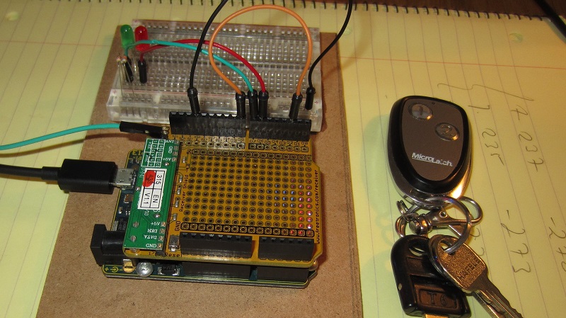
Data Pin: The receiver shield has only one data pin: it reads high when the carrier wave is detected and low when the carrier wave is not detected. The pin is connected to D8 on the Arduino, but I also connected it to D2 so I can attach an interrupt and receive data that way (this is the orange jumper wire in the picture).
Antenna: There is also pin connection for the antenna, this is a piece of wire about 15 to 17 cm in length that is attached to a pin on the side (the green wire in the picture). Without an antenna wire, the receiver has very poor performance, so make sure you don’t forget about it.
Status LEDs: The 433Mhz receiver shield was supposed to have two general purpose leds connected to D6 and D7, but these didn’t work on the shield I got, perhaps they were faulty. I wired instead two external leds on the breadboard, a green one which lights up for the preamble and a red one which lights up when data is received.
Data Transmission Overview
The 433Mhz transmission uses On-Off Keying modulation, which is a type of Amplitude-Shift keying modulation. The two terms are abbreviated as OOK and ASK respectively, but, in practical terms, what this means is that, to transmit a digital signal of ones and zeros, the 433Mhz carrier wave is ON, or transmitted, when the digital signal is 1 and it is OFF when the digital signal is 0. It looks like this:
Theoretically, data can be transmitted directly over the wire simply by controlling the on-off state of the transmitter using a shift register, but this would create problems since long strings of ones or zeros would be difficult to detect by the receiver. Instead, the HCS200 encodes each bit using 3 clock cycles, where a 0 places the digital signal high for 2 clock cycles and low or one clock cycle, while a 1 places the digital signal high for one clock cycle and low for two clock cycles. Here is how it looks:

With this encoding, there are no long periods of ON or OFF transmissions, and a receiver can decode the transmission without having to have an accurate clock. For example, to transmit the number 240, which is 11110000 in binary, the signal pattern would look like this:
In addition to the patterns for 1 and 0, the HCS200 also uses a preamble signal: this signal is a sequence of ON and OFF periods of equal length. Since the encodings for 0 and 1 have different lengths for their ON and OFF periods, the preamble cannot be confused with a regular data and can be used by a receiver to detect the beginning of a transmission.
When it transmits, the HCS200 always sends 66 bits of data in a loop — the same 66 bits are send repeatedly while the button is pressed. Each individual transmission begins with a preamble signal. Following the preamble, there is a header time when the transmitter is silent and following the header, the 66 bits of data are sent — these are encoded as described above. The bits are split in two equal parts: 32 encrypted bits and 34 unencrypted bits or fixed bits , the contents of the bits are explained in the code word description below. After all the data is transmitted, there is another guard time where the transmitter is silent and this may be followed by another transmission:
Each HCS200 transmission forms a code word with the structure shown below. The encrypted part would need to be decrypted first and contains the sequence counter for the transmitter, which allows the receiver to determine if the received code word is valid or not. Decryption requires a decryption key, which is only known to the manufacturers, without this, the transmitter cannot be authenticated. The unencrypted part, however, contains the transmitter’s serial number as well as the status of its buttons (each transmitter can have up to 4 buttons).

The Software
The source code for this project is available on GitHub, in the Arduino_433Mhz, the sketch is named hcs200. The code sets up an interrupt handling routine for input pin D2, which processes the data from the 433Mhz shield. The main loop just looks for a received code word and prints it out.
The Arduino program begins running with the setup function. This function ensures that the pins are setup correctly, D8 and D2 as inputs from the 433Mhz shield and D6 and D7 as outputs to the lets on the breadboard. The setup code also sets up the pin2ISR as the function to be called when data on the input pin D2 changes, this function will be called when the input pin changes from 0 to 1 or from 1 to 0.
1 2 3 4 5 6 7 8 9 10 11 12 13 14 15 |
#define PREAMBLE_LED 7 #define DATA_LED 6 void setup() { Serial.begin(38400); // Board has the data bit wired to pin 8, and we bridge it to pin 2 to be // able to attach an interrupt. pinMode(8, INPUT); pinMode(2, INPUT); pinMode(PREAMBLE_LED, OUTPUT); pinMode(DATA_LED, OUTPUT); attachInterrupt(digitalPinToInterrupt(2), pin2ISR, CHANGE); Serial.print("Started listening\n"); } |
The pin2ISR maintains some global state about the state of the receive, since it is invoked each time the digital input changes. First, it maintains rx_state, which records the phase of the receive: RS_NOSYNC when no receive is in progress, RS_PREAMBLE when the preamble is being received, RS_DATA when the actual code word data is being received and RS_COMPLETED indicates that an entire code word has been received.
Received data is stored in rx_buf which is an array of three 32 bit numbers, which can hold a total of 96 bits. The HCS200 sends out only 66 bits, so this buffer is large enough. The next position in the receive buffer is stored in rx_bit_count, but since data is received bit-by-bit, this records the number of bits.
In order to determine what is a “long pulse” and what is a “short pulse”, the decoder needs to know the transmission clock period. This is stored in tx_clock and it is determined during the preamble phase which contains transitions every clock period.
Finally, last_timestamp and last_pulse_width are used to keep track of the previous timestamp and pulse width and it is used to decode the bits in the transmission.
1 2 3 4 5 6 7 8 9 10 11 12 13 14 15 16 |
enum RxState { RS_NOSYNC = 0, // Receiver is inactive RS_PREAMBLE = 1, // 50% duty cycle RS_DATA = 2, // DATA is being received RS_COMPLETED = 3 // Receive complete }; volatile char rx_state = RS_NOSYNC; char rx_bit_count = 0; uint32_t rx_buf[3]; unsigned tx_clock = 0; unsigned long last_timestamp = 0; unsigned last_pulse_width = 0; |
The pin2ISR function is shown below. It first determines the “pulse width” which is the time since the function was last called, and reads the state of the input pin. It may be useful to review the transmission pattern of the HCS200 to better understand what is happening:
Depending on the state of the receiver (the rx_state value), the pin2ISR function will do one of the following:
- if the receiver is inactive,
RS_NOSYNC, it looks for a long pulse width, this corresponds to a long silence before a transmission. If it finds one, it puts the receiver inRS_PREAMBLEstate. - In
RS_PREAMBLEstate, the receiver tries to determine the clock period ,tx_clock, by averaging the pulse widths. If it determines that the last pulse width was a long one, it switches the to start receiving the data bits. - In
RS_DATAstate, the receiver tries to decode the received bits. It does that by looking at the last two pulses: a long pulse followed by a short one represents a1and a short pulse followed by a long one represents a0(see how the logic 1 and 0 are encoded by the HCS200). In each case it stores the bit in the appropriate place inrx_buf. Once all bits are received, the state is changed toRS_COMPLETED, and the main program loop can now inspect the received code word. TheClassifyfunction is used to determine if a pulse is short,RB_SHORTor long,RB_LONGthis function is not shown here, it is available in the GitHub repository. - Note that the function does nothing while the receiver is in
RS_COMPLETEDstate — in this state, it waits for the main program loop to read the received data and to reset the state back toRS_NOSYNC, so a new code word can be received.
1 2 3 4 5 6 7 8 9 10 11 12 13 14 15 16 17 18 19 20 21 22 23 24 25 26 27 28 29 30 31 32 33 34 35 36 37 38 39 40 41 42 43 44 45 46 47 48 49 50 51 52 53 54 |
void pin2ISR() { unsigned long timestamp = micros(); unsigned long pulse_width = timestamp - last_timestamp; int pin = digitalRead(2); switch (rx_state) { case RS_NOSYNC: // "Sync" is a high pulse, folowed by a long low if (pin == 1 && pulse_width > 10000 && pulse_width < 50000) { rx_state = RS_PREAMBLE; tx_clock = last_pulse_width; } break; case RS_PREAMBLE: if (pulse_width < 2 * tx_clock) { tx_clock = (tx_clock + pulse_width) >> 1; } else if (pin == 1 && pulse_width > 1000) { // pulse_width was for a long low, switch to receiving data. rx_state = RS_DATA; rx_bit_count = 0; memset(rx_buf, 0, sizeof(rx_buf)); } else { rx_state = RS_NOSYNC; // Transmission error } break; case RS_DATA: if (pin == 1) { int first = Classify(last_pulse_width); int second = Classify(pulse_width); if (first == RB_LONG && second == RB_SHORT) { // Received a 1 bit int idx = rx_bit_count / 32; rx_buf[idx] >>= 1; rx_buf[idx] |= 0x80000000; rx_bit_count++; } else if (first == RB_SHORT && second == RB_LONG) { // Received a 0 bit int idx = rx_bit_count / 32; rx_buf[idx] >>= 1; rx_bit_count++; } else { // invalid pulse combination rx_state = RS_NOSYNC; } } if (rx_bit_count >= MAX_BITS) { rx_state = RS_COMPLETED; } break; } last_timestamp = timestamp; last_pulse_width = pulse_width; } |
The main program loop is really simple: It sets the leds on and off depending of the state of the receiver (rx_state) and checks if the state is RS_COMPLETED, in which case, it decodes the received data and prints it out to the serial port.
1 2 3 4 5 6 7 8 9 10 11 12 13 14 |
void loop() { digitalWrite(DATA_LED, rx_state == RS_DATA); digitalWrite(PREAMBLE_LED, rx_state == RS_PREAMBLE); if (rx_state == RS_COMPLETED) { if (rx_bit_count >= MAX_BITS) { Hcs200_keycode keycode; Hcs200Decode(rx_buf, &keycode); Hcs200Print(&keycode); } rx_state = RS_NOSYNC; } } |
Final thoughts
It was an interesting project to figure out how the remote keyfobs transmit the data, but it cannot be used for anything important. The keyfobs can be identified by their serial number and the code knows which buttons were pressed, however, since the encrypted part cannot be decrypted without a decryption key, the keyfobs cannot be authenticated and the receiver can never know if the received key code is authentic or fake.