Bike Trainer
I bought a bike trainer last June for indoor riding during winter (which in the southern hemisphere is in July and August.) and I decided to write virtual ride simulator to use it. The simulator would follow a predefined course on the map: the current position would advance based on the speed received from the trainer, and the application would control the resistance based on the slope at the current location.
The trainer itself comes with a basic control application which displays speed, power and cadence plus, it allows controlling the resistance manually. Different vendors also provide monthly subscriptions for more sophisticated training applications. However, I find it more interesting and challenging to write my own application to control the trainer. In doing so, I learned how to communicate with ANT+ devices, how to extend the pasteboard% object to display a map on the background and a few things about the GPX tracks.
Running the application
Equipment You need the following equipment to run the application:
- An ANT+ FE-C capable bike trainer (all recent trainers should work)
- A bike to put on the trainer
- An ANT+ Heart Rate Monitor (optional)
- An ANT+ USB dongle
GPX Track You will also need a GPX file, which contains the GPS track to ride. If you don’t have any, here are two sample ones:
Telemetry Server Communicating with the application is done using a separate application, a TelemetryServer. Follow the instructions in that projects README file to build and run it.
Source Code for the application is on the bike-trainer branch of the ActivityLog2 project, with all relevant files in the bike-trainer folder.
To run the application, first start the telemetry server, than open the bike-trainer.rkt file in DrRacket and click “Run” (or Ctrl-R). You will need to connect to the telemetry server by typing the following in the Racket interaction window (7500 is the TCP port number it will connect to):
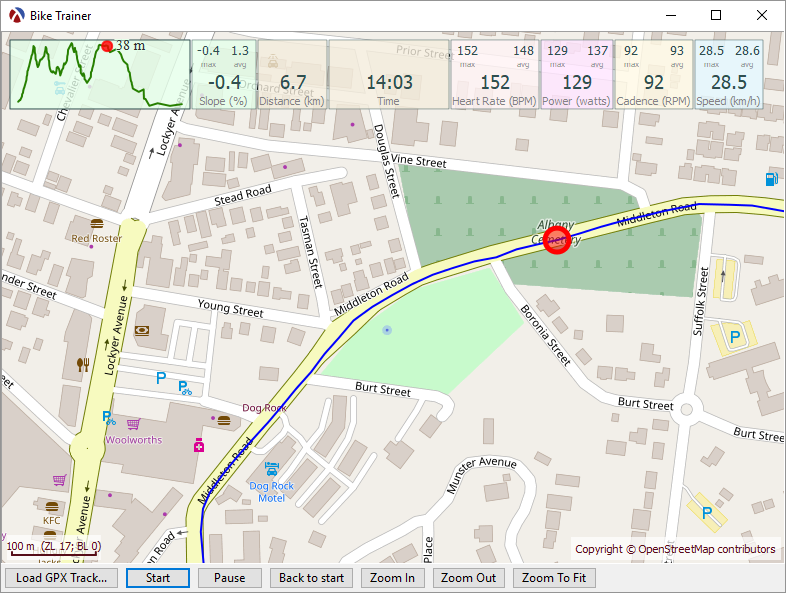
(connect 7500)Once that is done, the live telemetry data should show up on the top of the window. You can load a GPX track, click “Start” and start pedaling. The current location should advance on the map and the trainer resistance will change depending on the slope at the current location.
Running the application in demo mode
The demo-telemetry-server.rkt utility can be used to supply pre-defined telemetry values to the bike trainer application. This can be used to test the application without a bike trainer, or to simply run the application in demo mode.
To run the server, you will need a CSV file with telemetry data. A CSV file in the required format can be exported by selecting an existing activity and using the “Activity / Export track data (CSV)…”. You can also download a sample CSV file here.
The server can be run from the command line as:
racket demo-telemetry-server.rkt -f telemetry-data.csvAlternatively, the server can send telemetry directly from an existing session from the ActivityLog2 database. You will need the session id, which you can find by opening a session and using the “Activity/Copy session id to clipboard…” menu item. You can than use the following command:
racket demo-telemetry-server.rkt -s SESSION-ID
Once started, the bike-trainer application will connect to this server to receive telemetry values.
Technical details
The implementation is on the bike-trainer branch of the ActivityLog2 project, with all relevant files in the bike-trainer folder.
As part of the ActivityLog2 application, I already had the most important ingredient: a map widget with all the necessary map utilities. I decided to use a pasteboard% for the main application window, with the map being displayed as the background and all the other views implemented as snip% objects.
A “current location” concept was added to the map-widget%: when a current location is set using set-current-location, a red circle will be drawn at that location. Also the current location is “tracked”, meaning that the map is slowly panned so that the current location is always displayed on the screen. This is currently non-configurable, see track-current-location.
Also, the map-widget% was updated to act as a pasteboard%. The map is drawn as the pasteboard background, and the pasteboard can be accessed using get-pasteboard and snips can be inserted. Mouse handling has changes: click and drag events are used to pan the map around and mouse events with the “Control” key pressed are passed to the pasteboard%. This means that selecting and moving snips around is done while the “control” key is pressed.
Training data is overlaid on top of the map using snips:
- a telemetry-snip% is used for each of the telemetry values (heart rate, power, speed, cadence, etc)
- an elevation-profile-snip% is used to display the elevation profile on the map
- a message-snip% is used to display messages
The simulation state (current location on the map and how it changes with the speed) is implemented in the sim-state.rkt file. A sim-state structure is defined containing all relevant data for the simulation along with functions to update it. I decided to experiment with “functional updating” of the state: all update functions return a new updated simulation state, rather than updating the existing state. This has resulted in elegant code in the simulation-task (see below)
The main application is in the bike-trainer.rkt file, which sets up the widgets and starts the simulation-task procedure in a separate thread. This procedure reads telemetry data from the trainer and updates the simulation state.
Communicating with the trainer
The bike trainer sends and receives data using the wireless ANT+ protocol, the same as my heart rate monitor and power meter on the bike. On the PC side, the data is sent and received using an ANT+ USB dongle (an ANT Stick). The ANT+ protocol documentation is available from www.thisisant.com, although you have to sign up and upgrade your account to “Adopter”. This costs nothing, but you need agree to keep all documents confidential and not further distribute the documentation.
The ANT+ communication part is implemented as a C++ server application, TrainerControl, the server accepts TCP connections and sends telemetry data (heart rate, power, speed and cadence) and receives commands over that connection. It uses libusb for the USB communication, since I wanted my code to be portable. The application currently builds on Windows, but ultimately, I would like to port it to a Raspberry PI running Linux.
Why not use Racket for the ANT+ communication? I could have used the Racket Foreign Function Interface (FFI) to provide bindings for libusb, and write the entire ANT+ implementation in Racket. I didn’t do it mostly because I took the path of least resistance: I already had experience using libusb from C++ and had no experience with using Racket FFI.
Next Steps
This application is very much in its early stages, only a proof of concept. I’d like to expand it to include structured workouts and data recording as well as package it into an application that is ready to use. However, all this will have to wait until next year: summer has arrived here in Australia and I can start riding outdoors again.